设计说明书
总字数:10000+
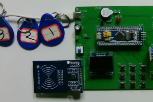
本文介绍了一个基于RFID、红外避障管、按键和OLED的自动化生产线监测系统。系统采用了altium designer 2013进行原理图和PCB的绘制,Keil5进行程序的编程,Visio进行流程图的绘制;并采用了分模块进行设计的方法,通过软硬件配合,实现了对工人的自动识别、材料缺货的报警、后台监工的审核功能以及数据的显示等功能。在本系统中,采用了RFID技术来识别三个工人是否正常上班。每个工人都有一张ID卡,当卡片放到读卡器上时,进行打卡。每个工人配备一个按键,代表完成了一件工作。这样,监控系统可以实时地了解到工人的生产量和工作状态。为了及时发现材料是否足够,系统中加入了红外避障管。当材料不足以完成下一步操作时,该避障管就会被触发,发出声光报警,提示工人及时更换材料,并避免因缺材料导致的生产故障。为了确保产品的质量和工人的效率,系统设置了后台监工。监工处有六个按键,分为三组对应三个工人,每组两个按键,有“合格”键和“返工”键。当工人完成一个件后,需要向监工汇报情况,监工根据实际情况点击对应的按键。如果工作合格,则该产品数量增加并可以继续做下一个;如果工作不合格,则工人需要重新做这个件,并按下自己的按键汇报情况,此时数量不增加,后台依旧进行评价,只有在工作合格后才能做下一个。这样,系统可以进行下一天的监测工作,准确统计每个工人的产量。OLED屏幕将显示三个工人的状态、件数、合格或返工等信息。这样,操作人员可以实时地了解生产线上的情况,及时处理问题,避免产生意外情况。该系统采用先进的技术手段,包含多项功能,可以实时监测工人的上班情况、材料的充足情况、产品的质量情况等等。该系统的应用,提高了生产效率,保证了产品质量,极大地方便了管理者对工作进度的掌控及监督。
关键词:流水线;传感器;人机界面;实时监控
This paper introduces an automatic production line monitoring system based on RFID, infrared obstacle avoidance tube, button and OLED. The system uses altium designer 2013 to draw the schematic diagram and PCB, Keil5 to program, and Visio to draw the flow chart. The method of sub-module design is adopted, and the automatic identification of workers, the alarm of material shortage, the audit function of background supervisor and the display of data are realized through the cooperation of hardware and software. In this system, RFID technology is used to identify whether three workers are working normally. Each worker has an ID card and punches it when the card is placed on the card reader. Each worker is equipped with a button to represent the completion of a job. In this way, the monitoring system can know the production volume and working status of workers in real time. In order to find out whether the material is sufficient in time, infrared obstacle avoidance tubes are added to the system. When the material is not enough to complete the next step, the obstacle avoidance tube will be triggered, and the sound and light alarm will be issued to prompt the worker to replace the material in time and avoid the production failure caused by the lack of material. In order to ensure the quality of products and the efficiency of workers, the system sets up a background supervisor. There are six keys in the supervisor’s office, divided into three groups corresponding to three workers, each group of two keys, there are “qualified” keys and “rework” keys. When the worker completes a piece, he needs to report the situation to the supervisor, and the supervisor clicks the corresponding button according to the actual situation. If the work is qualified, the quantity of the product is increased and can continue to do the next one; If the work is not qualified, the worker needs to do this piece again, and press their own button to report the situation, at this time the number does not increase, the background is still evaluated, only after the work is qualified to do the next. In this way, the system can monitor the next day and accurately count the output of each worker. The OLED screen will display information such as the status, number of pieces, qualification or rework of the three workers. In this way, the operator can understand the situation on the production line in real time, deal with problems in a timely manner, and avoid accidents. The system uses advanced technical means, including a number of functions, can real-time monitoring of workers to go to work, material adequacy, product quality and so on. The application of this system improves the production efficiency, guarantees the product quality, and greatly facilitates the manager to control and supervise the work progress.
Key words:pipeline; Sensor; Man-machine interface; Real-time monitoring
目 次
摘 要
Abstract
1 引言
1.1 课题研究的意义和背景
1.2 国内外研究现状
1.2.1 国内研究现状
1.2.1 国内研究现状
1.3 课题研究的主要内容和工作
2 整体硬件的设计与实现
2.1 系统整体结构
2.2 方案论证与比较
2.2.1 主控芯片选择
2.2.2 显示模块方案
3 具体硬件设计
3.1 主控模块电路
3.2 RFID检测电路模块
3.3 红外避障电路模块
3.4 显示电路模块
3.5 按键电路模块
3.6 声光报警模块
4 系统程序设计
4.1 编程软件介绍
4.2 系统主流程设计
4.3 独立按键
4.4 OLED显示流程设计
5实物制作过程
5.1 PCB的制作流程
5.2 调试过程
5.2.1硬件调试
5.2.2软件调试
5.3实物功能测试
5.3.1 RFID上下班打卡实物测试
5.3.2 物料是否缺少实物测试
5.3.3 工人工作数量实物测试
5.3.4 工人工作合格判断实物测试
6 结论
致 谢
参考文献
附录1 硬件原理图
附录2 硬件PCB图
附录3 部分源程序
购买后可查看具体内容!

