设计说明书
总字数:14000+
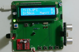
传统风扇存在的功能单一、智能化程度低等问题,为了弥补传统风扇的缺点,基于相关技术设计一款智能调温风扇是大势所趋。该系统采用了模块化设计思路,采用STC89C52单片机作为主控芯片对风扇进行控制,通过单片机与外围电路连接,实现温度、红外光电、距离等信号采集,并将采集到的数据发送至主控制器进行处理分析,实现了风扇自动开启与关闭等功能,并根据实际情况进行不同档次的运转。还增加手动控制功能,使其可在任意时间内随意打开或关闭风扇,同时也可根据需要对相关模块进行修改以满足不同用户需求。测试结果表明,该风扇控制系统能够根据环境温度和人体红外信号实现风扇的自动启停和调速,具有一定的应用价值。
关键词: 风扇;数据监测;单片机;传感器;显示屏
With the improvement of the national economy, the number of taxis is increasing, and the meter provides a basis for the regular maintenance, maintenance and scrapping of vehicles. Aiming at the problems of lack of conditions, interference factors and low reliability, this paper develops an intelligent taxi meter by using single chip microcomputer technology, and achieves intelligent pricing function under the premise of reducing cost.This design uses STC89C52 single chip microcomputer as the main control chip to design a more intelligent taxi meter, which effectively solves the problem that night and day charges are not the same, the design has two modes, day and night, the starting price of 8 yuan during the day, more than 2.5 kilometers for 1.7 yuan/kilometer, when the customer arrives, When the driver presses pause, the fare stops, can be cleared after the customer gets off, and then restarted when the next customer gets on. At night, the starting price is 9 yuan and 1.7 yuan per kilometer after 2.5 kilometers. Through the combination of software and hardware, the design can finally solve the problem of the current taxi charging, and the taxi driver can view the current time, speed, total kilometers, unit price, total amount through the display screen, and the design stability is also strong, the cost of equipment is low, and the reliability is also strong.
Keywords Taxi, meter, MCU, night mode, day mode
目 录
摘 要
Abstract
第一章 设计概述
1.1 研究背景及其意义
1.2 国内外研究现状
1.3 此次设计实现的功能
第二章 系统设计方案
2.1 系统设计方案
2.2 主要元器件选择
2.2.1 主控芯片方案
2.2.2 显示模块方案选择
2.2.3 按键模块方案选择
第三章 硬件设计
3.1 主控模块电路
3.2 电机驱动模块电路
3.3DS18B20温度检测模块电路
3.4人体红外检测模块
3.5HC-SR04超声波避障模块电路
3.6 LCD1602显示模块电路
3.7 按键模块
第四章 系统程序设计
4.1 编程软件介绍
4.2 系统主流程设计
4.3 独立按键
4.4 温度检测模块子流程
4.5 直流电机-MX1508驱动模块子流程
4.6 超声波检测模块子流程
4.7 LCD1602液晶显示子流程
第五章 仿真测试
5.1 整体仿真图
5.2 上电仿真测试
5.3 温度调节仿真测试
5.4 是否有人仿真测试
5.5 超声波模块仿真测试
第六章 实物测试
6.1实物焊接
6.2 上电实物测试
6.3 温度调节实物测试
6.3 是否有人实物测试
6.3 超声波模块实物测试
总结
参考文献
附录
附录一:原理图
附录二:PCB
附录三:主程序
购买后可查看具体内容!

