
设计说明书
总字数:17000+
本论文介绍了基于STC89C52单片机的温室大棚设计项目。该设计利用多个传感器实时监测温室环境参数,包括环境温度、土壤湿度、CO2浓度和光照强度,并根据预设的阈值进行相应的控制操作。当环境温度低于设定最小值时,系统启动加热器进行升温;当温度高于设定最大值时,系统启动风扇进行降温。土壤湿度低于设定最小值时,系统启动水泵进行加水;湿度高于设定最大值时,系统启动风扇进行除湿。CO2浓度高于设定最大值时,系统启动风扇进行通风。光照强度低于设定最小值时,系统启动补光;光照强度高于设定最大值时,系统打开遮阳棚。用户可以通过按键设置各个阈值,并通过LCD1602显示屏实时显示监测数据。这个基于单片机的温室大棚设计实现了智能化的环境监测和控制,提供了便捷的操作和监测方式,有望提高温室种植的效率和产量。
关键字:单片机;温室大棚;STC89C52;环境监测;智能控制;LCD1602显示屏。
This paper presents a design project of a greenhouse using the STC89C52 microcontroller. The design utilizes multiple sensors to monitor real-time environmental parameters in the greenhouse, including ambient temperature, soil moisture, CO2 concentration, and light intensity. Based on pre-set threshold values, the system performs corresponding control operations. When the temperature falls below the minimum threshold, the system activates a heater for temperature regulation. Conversely, when the temperature exceeds the maximum threshold, a fan is triggered for cooling. Similarly, when soil moisture drops below the minimum threshold, a water pump is activated for irrigation, and if it surpasses the maximum threshold, a fan is employed for dehumidification. In the case of CO2 concentration exceeding the maximum threshold, a fan is employed for ventilation. Additionally, the system triggers supplementary lighting when light intensity falls below the minimum threshold and opens the shading net when it surpasses the maximum threshold. Users can interact with the system through buttons to set various threshold values, and real-time monitoring data is displayed on an LCD1602 screen. This microcontroller-based greenhouse design realizes intelligent environmental monitoring and control, providing convenient operation and monitoring methods. It is expected to enhance efficiency and yield in greenhouse cultivation.
Keywords: Microcontroller, Greenhouse, STC89C52, Environmental Monitoring, Intelligent Control, LCD1602 Display.
目 录
摘 要
Abstract
第1章 引 言
1.1 选题背景及实际意义
1.2 国内外研究现状
1.3 本论文研究目标
第2章 系统设计方案
2.1 主要元器件选择
2.1.1 主控芯片选择
2.1.2 温度检测模块方案选择
2.1.3 光照强度检测模块方案选择
2.1.4 显示块方案选择
2.2 整体设计方案
第3章 硬件设计
3.1 主控电路模块
3.2 温度检测模块电路
3.3 光照强度模块电路
3.4 土壤湿度检测模块电路
3.5 CO2检测模块电路
3.6 显示模块电路
3.7 步进电机模块电路
3.8 继电器模块电路
3.9 按键模块电路
第4章 系统程序设计
4.1 编程软件介绍
4.2 系统主流程设计
4.3 独立按键
4.4 LCD1602液晶显示子流程
4.5步进电机子流程
4.6 A/D模数转换子流程
第5章 仿真测试
5.1 整体仿真测试图
5.2 大棚温度测控仿真测试
5.3 大棚湿度测控仿真测试
5.4 大棚光照强度测控仿真测试
5.5 CO2测控仿真测试
第6章 实物测试
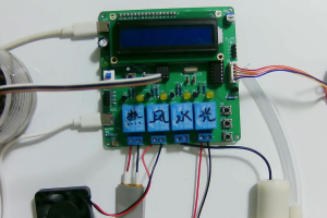
6.1 整体实物测试图
6.2 大棚温度测控实物测试
6.3 大棚湿度测控实物测试
6.4 大棚光照强度测控实物测试
6.5 CO2测控实物测试
总结与展望
参考文献
致 谢
附录一: 原理图
附录二:PCB
附录三:主程序
购买后可查看具体内容!