
项目编号:mcuclub-jj-014
STM32单片机实物设计简介:
单片机类型:STM32F103C8T6
具体功能:
1、通过DHT11检测鞋柜温湿度,当温度低于设置值,进行加热,当湿度高于设置值,进行加热和通风;
2、通过GP2Y10检测粉尘浓度,当粉尘浓度值大于设置最大值,进行通风
3、通过MQ-135检测鞋柜内氨气,过高时启动紫外线杀菌
4、通过霍尔传感器检碗柜门状态,关闭时,自动打开消毒灯,打开时,消毒灯关闭
5、通过光敏电阻检测光照值,当光照值低于设置最小值且鞋柜门打开,则LED照明灯自动打开
6、通过MQ-2检测烟雾值,当烟雾值大于设置最大值,进行蜂鸣器报警
7、通过按键设置各阈值
8、通过显示屏显示测量值
扩展功能:通过蓝牙模块将测量数据发送到手机端,并可以控制加热、除湿、通风、消毒、照明以及模式切换
实物演示视频:
打开视频声音方法:鼠标放在视频中,点击右下角小喇叭图形即可;视频放大后不清晰,可将鼠标放在视频上,点击“进入哔哩哔哩,观看更高清”
电子版资料介绍视频:
打开视频声音方法:鼠标放在视频中,点击右下角小喇叭图形即可;视频放大后不清晰,可将鼠标放在视频上,点击“进入哔哩哔哩,观看更高清”
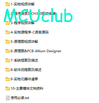
电子版实物资料预览
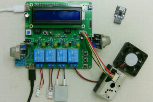
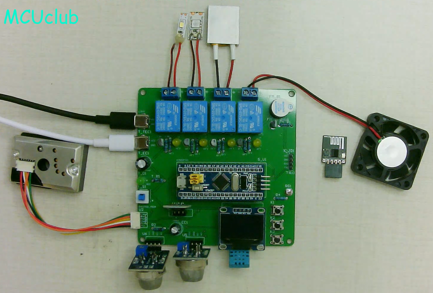
实物图
底板:底板在嘉立创进行打板,为绿色PCB板,两层板,厚度1.2,上下覆铜接地。元器件基本上为插针式,个别降压芯片会使用贴片式。
供电接口:TYPE-C
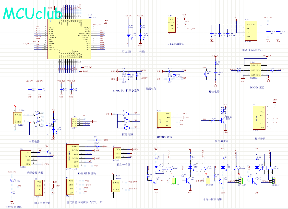
原理图
软件版本:AD2013 (本站提供该软件免费下载链接)
电路连线方式:网络标号连线方式
注意:原理图只是画出了模块的引脚图,而并不是模块的内部结构原理图
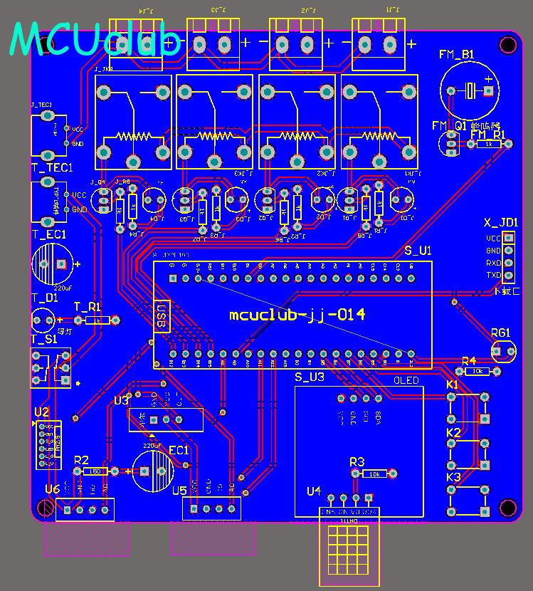
PCB图
软件版本:AD2013 (本站提供该软件免费下载链接)
PCB图是由原理图导出,封装很大一部分都是作者自己绘制,不提供封装库,只提供连接好的源文件,可以直接在嘉立创进行打板。两层板,上下覆铜接地。
注意:PCB图中间有一个项目编号,隐藏在单片机底座下,插入单片机后不会看到。如果想截没有项目编号的PCB图,可在PCB源文件中点击删除。另外,如果想在实物PCB板上加自己的信息(比如日期、学号、姓名等),可联系客服。
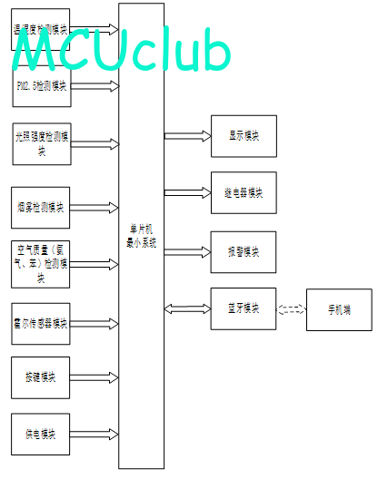
系统框图
绘制软件:VISIO (本站提供该软件免费下载链接)
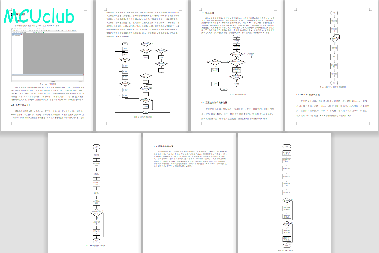
软件设计流程
绘制软件:VISIO (本站提供该软件免费下载链接)
开题报告
下图为开题报告整体框架模板,基本上所有项目的开题报告格式都如下所示,但由于部分院校要求不一致,可能有一小部分格式有所变动。
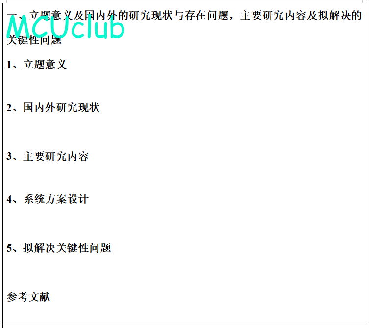
购买后可查看具体内容!
设计说明书
总字数:20000+
摘 要
当前我国综合国力显著增强,人民生活水平日益提高,鞋类产品消费量快速增长,鞋文化正成为当代潮流的一个重要分支。然而鞋子在穿着过程中会产生诸多卫生问题,在长期穿着后鞋内处于闷热潮湿的微环境,引发脚气足癣等皮肤病。新型冠状病毒在全球爆发,有研究发现鞋子也可能成为传播疾病的媒介,但忽视了对其进行清洁消毒。鞋柜作为存储鞋子的家具产品,其内部阴暗封闭,非常适宜细菌的生存与繁殖。如今单一存储功能的鞋柜已经不能满足人们的卫生健康需求,集智能化、绿色化于一体的消毒鞋柜将成为未来市场的趋势。本文以鞋柜作为研究对象,采用单片机技术对其进行设计,分为软件设计和硬件设计,硬件设计:采用STM32单片机作为主控芯片,采用DHT11检测鞋柜中的温湿度,采用GP2Y10检测鞋柜灰尘浓度,采用霍尔传感器检测用户是否需要打开鞋柜,采用OLED显示屏将检测的数据传输到用户的手机上,用户可以通过按键对其参数值进行设计;软件设计:采用Keil5作为此次设计程序编程软件,采用AD作为此次设计的原理图和PCB的绘制软件,采用stc-isp作为此次设计程序的烧录软件,采用Visio作为此次设计的流程图绘制软件;通过软硬件配合进行设计,实现对用户鞋柜中的温湿度进行控制,对鞋柜中的灰尘浓度进行控制,检测到用户需要打开鞋柜时,自动进行打开。
关键词:鞋柜;温湿度;霍尔传感器;光照检测;灰尘浓度
Abstract
At present, China’s comprehensive national strength has been significantly enhanced, the people’s living standard has been improved day by day, and the consumption of footwear products has been growing rapidly. Shoe culture is becoming an important branch of the contemporary trend. However, many health problems will occur in the wearing process of shoes. After long-term wearing, the shoes are in a hot and humid microenvironment, causing skin diseases such as athlete’s foot and athlete’s foot. Novel coronavirus has broken out all over the world. Some studies have found that shoes may also become a vector of disease, but they have neglected to clean and disinfect them. As a furniture product for storing shoes, the shoe cabinet is dark and closed inside, which is very suitable for the survival and reproduction of bacteria. Nowadays, shoe cabinets with a single storage function can no longer meet people’s health needs, and disinfection shoe cabinets with intelligent and green features will become the trend of the future market.In this paper, the shoe cabinet is taken as the research object, and is designed with the single-chip technology, which is divided into software design and hardware design. Hardware design: STM32 single-chip is used as the main control chip, DHT11 is used to detect the temperature and humidity in the shoe cabinet, GP2Y10 is used to detect the dust concentration in the shoe cabinet, Hall sensor is used to detect whether the user needs to open the shoe cabinet, and OLED display is used to transmit the detected data to the user’s mobile phone, The user can design the parameter value by pressing the key; Software design: Keil5 is used as the program programming software of this design, AD is used as the drawing software of the schematic diagram and PCB of this design, stc isp is used as the burning software of this design program, and Visio is used as the flow chart drawing software of this design; It is designed through the cooperation of software and hardware to control the temperature and humidity in the user’s shoe cabinet, control the dust concentration in the shoe cabinet, and automatically open the shoe cabinet when it is detected that the user needs to open it.
Key words: shoe cabinet; Temperature and humidity; Hall sensor; Light detection; Dust concentration.
目 录
摘 要
Abstract
第1章 绪论
1.1 选题背景及实际意义
1.2 国内外研究现状
1.3 本论文研究目标
第2章 系统设计方案
2.1 主要元器件选择
2.1.1 主控芯片方案选择
2.1.2 显示模块方案选择
2.1.3 温湿度检测模块方案选择
2.2 整体设计方案
第3章 硬件设计
3.1 单片机最小系统
3.1.1 主控模块电路
3.1.2 晶振电路
3.1.3 复位电路
3.1.4 电源电路
3.1.5 下载电路
3.2 显示模块电路
3.3 温湿度检测模块电路
3.4 灰尘浓度检测模块电路
3.5MQ-2烟雾检测模块电路设计
3.6光敏电阻检测模块电路
3.7霍尔传感器模块电路
3.9继电器模块电路
3.10空气质量检测模块(氨气、苯)
3.11 独立按键电路
3.12蜂鸣器报警模块
3.13蓝牙模块(ECB02)
第四章 系统程序设计
4.1 编程软件介绍
4.2 系统主流程设计
4.3 独立按键
4.4 温湿度检测模块子流程
4.5 GP2Y10模块子流通
4.6 蓝牙模块子流程
第5章 实物测试
5.1 实物调试部分
5.2 整体焊接实物
5.3 上电实物测试
5.4温度检测实物测试
5.5 湿度检测实物测试
5.6 PM2.5检测实物测试
5.7氨气检测实物测试
5.8 烟雾浓度检测实物测试
5.8 光照强度检测实物测试
5.9 柜门状态实物测试
结论
参 考 文 献
致谢
附录
附录1:原理图
附录2:PCB
附录3:主程序
购买后可查看具体内容!
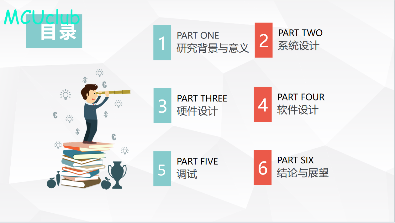
答辩PPT
下图为答辩PPT整体框架模板,基本上所有项目的答辩PPT格式都如下所示,但由于部分院校要求不一致,可能有一小部分格式有所变动。


购买后可查看具体内容!