
项目编号:mcuclub-hj-014
51单片机实物设计简介:
单片机类型:STC89C52
具体功能:
1、通过PM2.5传感器检测粉尘浓度
2、通过按键设置PM10浓度阈值,有最低启动值,中启动值和高启动值,当浓度低于最低启动值,不进行降尘,当浓度在低启动值和中启动值之间,则一个水泵启动;当浓度在中启动值和高启动值之间,则二个水泵启动;当浓度大于高启动值,则三个水泵启动;
3、通过按键设置各阈值,并能控制三个继电器的工作、切换模式
4、通过显示屏显示数据
扩展功能:通过蓝牙模块将测量数据发送到手机端,并可以控制三个继电器的工作、切换模式
实物演示视频:
打开视频声音方法:鼠标放在视频中,点击右下角小喇叭图形即可;视频放大后不清晰,可将鼠标放在视频上,点击“进入哔哩哔哩,观看更高清”
仿真演示视频:
打开视频声音方法:鼠标放在视频中,点击右下角小喇叭图形即可;视频放大后不清晰,可将鼠标放在视频上,点击“进入哔哩哔哩,观看更高清”
电子版资料介绍视频:
打开视频声音方法:鼠标放在视频中,点击右下角小喇叭图形即可;视频放大后不清晰,可将鼠标放在视频上,点击“进入哔哩哔哩,观看更高清”
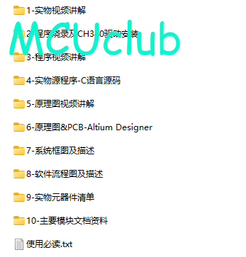
电子版实物资料预览
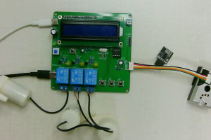
实物图
底板:底板在嘉立创进行打板,为绿色PCB板,两层板,厚度1.2,上下覆铜接地。元器件基本上为插针式,个别降压芯片会使用贴片式。
供电接口:TYPE-C

电子版仿真资料预览
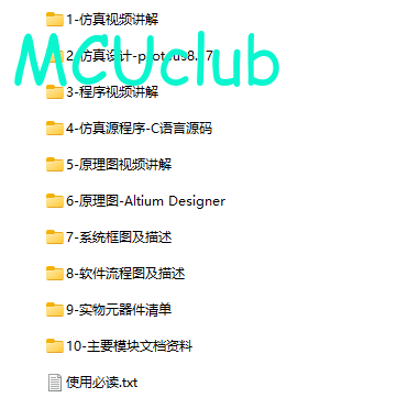
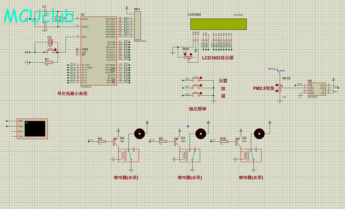
仿真图
仿真软件版本:proteus8.17 (本站提供该软件免费下载链接)
电路连线方式:网络标号连线方式
注意:部分实物元器件仿真中没有,仿真中会用其他工作原理相似的元件代替,这样可能导致实物程序和仿真程序不一样
原理图
软件版本:AD2013 (本站提供该软件免费下载链接)
电路连线方式:网络标号连线方式
注意:原理图只是画出了模块的引脚图,而并不是模块的内部结构原理图

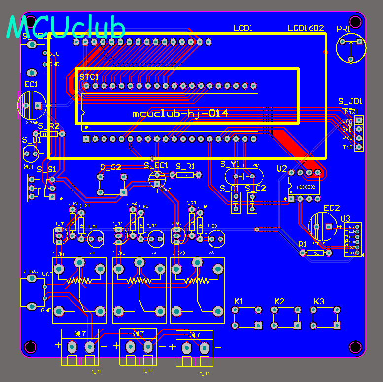
PCB图
软件版本:AD2013 (本站提供该软件免费下载链接)
PCB图是由原理图导出,封装很大一部分都是作者自己绘制,不提供封装库,只提供连接好的源文件,可以直接在嘉立创进行打板。两层板,上下覆铜接地。
注意:PCB图中间有一个项目编号,隐藏在单片机底座下,插入单片机后不会看到。如果想截没有项目编号的PCB图,可在PCB源文件中点击删除。另外,如果想在实物PCB板上加自己的信息(比如日期、学号、姓名等),可联系客服。
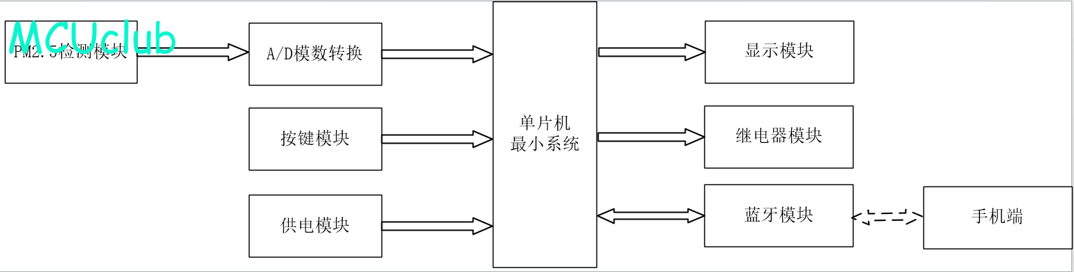
系统框图
绘制软件:VISIO (本站提供该软件免费下载链接)
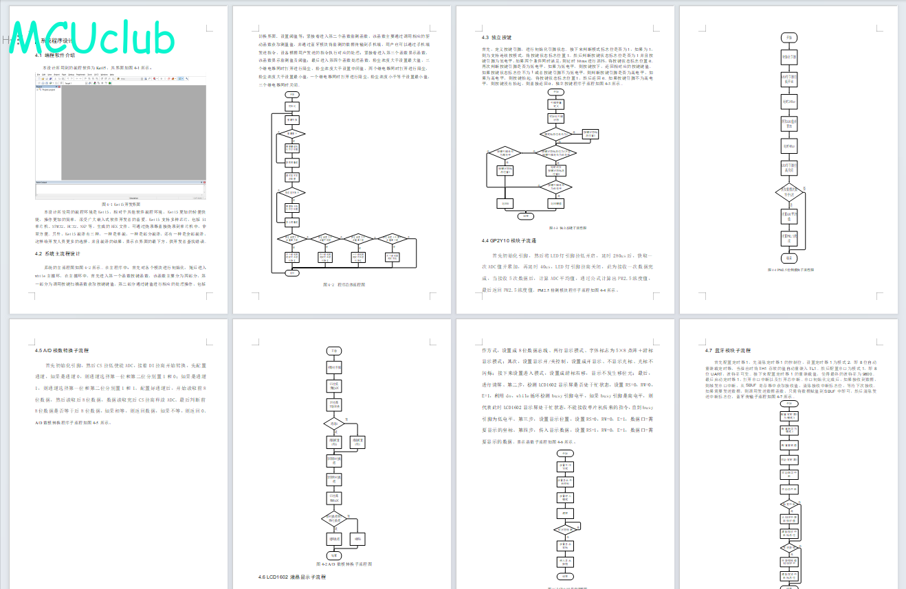
软件设计流程
绘制软件:VISIO (本站提供该软件免费下载链接)
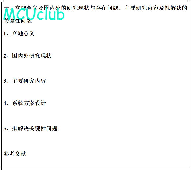
开题报告
下图为开题报告整体框架模板,基本上所有项目的开题报告格式都如下所示,但由于部分院校要求不一致,可能有一小部分格式有所变动。
购买后可查看具体内容!
设计说明书
总字数:13000+
摘 要
随着我国经济的迅速发展,工业化进程的加快,在建工程项目增多,雾霾、扬尘等污染也逐步成为影响国家生态环境的主要因素。建筑工地扬尘污染物为PM2.5,是城市雾霾天气和区域扬尘污染的主要来源之一。各级政府越来越重视建筑工地扬尘污染的控制,要求建筑工地配备扬尘污染监测系统。国内现有的施工扬尘污染监测方法一般由扬尘颗粒污染物监测仪组成,主要分布在在建工程围挡的四周和出入口处,其监测数据通过物联网实时反馈给政府监管部门,但监测效果受天气因素影响往往误差较大,监测周期长,难以为监管部门提供准确便捷的扬尘污染监测方法。因此,有必要探索一种可视化程度高、施工扬尘监测识别结果可信的扬尘监测并实时进行处理方法,对提高政府监管部门监测施工扬尘污染能力,帮助控制扬尘污染扩散具有一定的理论意义和应用价值。论文分析了建筑工地扬尘污染特征,总结了施工扬尘的来源,以在建工地场地内的传感器监测数据来源做扬尘污染监测分析;根据监测的数据自动控制水泵进行工作,从而实现降尘,且可以将检测的数据通过蓝牙传输到手机端,通过手机端可以控制水泵进行工作。
关键词:建筑降尘;PM2.5;水泵;测控;蓝牙
Abstract
With the rapid development of Chinese economy, the acceleration of industrialization and the increase of construction projects, haze, dust and other pollution gradually become the main factors affecting national ecological environment. The construction site dust pollutant is PM2.5, which is one of the main sources of urban haze weather and regional dust pollution. Governments at all levels pay more and more attention to dust pollution control at construction sites and require construction sites to be equipped with dust pollution monitoring systems. The existing construction dust pollution monitoring methods in China generally consist of dust particle pollutant monitoring instruments, which are mainly distributed around the enclosure and at the entrance and exit of construction projects under construction. The monitoring data are fed back to the government regulatory authorities in real time through the Internet of Things. However, the monitoring effect is affected by weather factors, and the monitoring period is long. It is difficult to provide accurate and convenient monitoring methods for dust pollution for regulatory authorities. Therefore, it is necessary to explore a dust monitoring and real-time processing method with high visualization degree and reliable construction dust monitoring and identification results, which has certain theoretical significance and application value for improving the ability of government supervision departments to monitor construction dust pollution and help control the diffusion of dust pollution.This paper analyzes the characteristics of construction site dust pollution, summarizes the sources of construction dust, and analyzes the dust pollution monitoring data from sensors in the construction site. According to the monitoring data, the water pump can be automatically controlled to work, so as to realize dust removal. Moreover, the detected data can be transmitted to the mobile phone through Bluetooth, through which the water pump can be controlled to work.
Key words: construction dust reduction; PM2.5; Water pump; Measurement and control; bluetooth
目 录
摘 要
Abstract
第 1 章 概述
1.1 研究背景及其研究意义
1.2 国内外工地降尘发展现状
1.2.1 国外现状及发展现状
1.2.2 国内现状及发展
1.3 主要研究内容
第2章 系统方案设计
2.1 主要元器件选择
2.1.1 主控模块方案选择
2.1.2 显示模块方案选择
2.2 系统总体设计思路
第3章 硬件电路
3.1 主控模块电路
3.2 PM2.5采集模块
3.3 显示模块电路
3.4 继电器模块电路
3.5 按键模块电路
3.6 蓝牙模块电路
第4章 软件设计
4.1 编程软件介绍
4.2 系统主流程设计
4.3 独立按键
4.4 GP2Y10模块子流通
4.5 A/D模数转换子流程
4.6 LCD1602液晶显示子流程
4.7 蓝牙模块子流程
第五章 仿真测试
5.1 整体仿真测试
5.2 PM2.5测控仿真测试
5.3 蓝牙测控仿真测试
第六章 实物测试
6.1 整体实物测试
6.2 PM2.5测控实物测试
6.3 蓝牙测控实物测试
第 7 章 结论与展望
7.1 结论
7.2 展望
致谢
参考文献
附录
附录一:原理图
附录二:PCB
附录三:主程序
购买后可查看具体内容!
答辩PPT
下图为答辩PPT整体框架模板,基本上所有项目的答辩PPT格式都如下所示,但由于部分院校要求不一致,可能有一小部分格式有所变动。


购买后可查看具体内容!